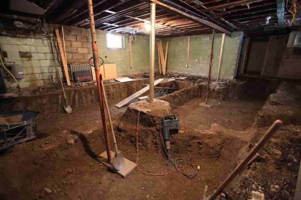
The beam and base method of underpinning is a more technically advanced adaptation of traditional mass concrete underpinning. A reinforced concrete beam is constructed below, above or in replacement of the existing footing. The beam then transfers the load of the building to mass concrete bases, which are constructed at designed strategic locations. Base sizes and depths are dependent upon the prevailing ground conditions. Beam design is dependent upon the configuration of the building and the applied loads. Anti-heave precautions are often incorporated in schemes where potential expansion of clay soils may occur. Mini-piles have the greatest use where ground conditions are very variable, where access is restrictive, where environmental pollution aspects are significant, and where structural movements in service must be minimal.
Mini-piled underpinning is generally used when the loads from the foundations need to be transferred to stable soils at considerable depths – usually in excess of 5 m (16 ft). Mini-piles may either be augured or driven steel cased, and are normally between 150 mm (5.9 in) and 300 mm (12 in) in diameter. Structural engineers will use rigs which are specifically designed to operate in environments with restricted headroom and limited space, and can gain access through a regular domestic doorway. They are capable of constructing piles to depths of up to 15 m (49 ft). The technique of mini-piling was first applied in Italy in 1952, and has gone through a plethora of different names, reflecting worldwide acceptance and expiration of the original patents.
The relatively small diameter of mini-piles is extremely distinctive of this type of underpinning and generally uses anchoring or tie backs into an existing structure or rock. Conventional drilling and grouting methods are used for this method of underpinning. These mini-piles have a high slenderness ratio, feature substantial steel reinforcing elements and can sustain axial loading in both senses. The working loads of mini-piles can sustain up to 1,000 kN (100 long tons-force; 110 short tons-force) loads. In comparison to Mass Concrete Underpinning, the engineering aspect of mini-piles is a bit more involved, including rudimentary engineering mechanics such as statics and strength of materials. These mini-piles must be designed to work in tension and compression, depending on the orientation and application of the design. In detail, attention with design must be paid analytically to settlement, bursting, buckling, cracking, and interface consideration, whereas, from a practical viewpoint, corrosion resistance, and compatibility with the existing ground and structure must be regarded.
Mini-piled underpinning schemes include pile and beam, cantilever pile-caps and piled raft systems. Cantilevered pile-caps are usually used to try and avoid disturbing the inside of a building and require the construction of tension and compression piles to each cap. These are normally linked by a beam. The pile and beam system usually involves constructing pairs of piles on either side of the wall and linking them with a pile cap to support the wall. Again, the pile caps are usually linked by reinforced concrete beams to support the entire length of the wall. Piled raft underpinning systems are commonly used when an entire building needs to be underpinned. The internal floors are completely removed, a grid of piles is installed and a reinforced concrete raft is then constructed over the complete floor level, picking up and fully supporting all external and internal walls.


